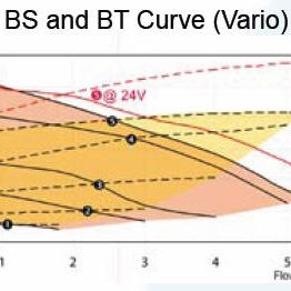
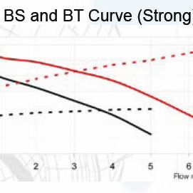
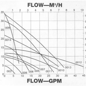
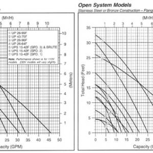
For proper operation, the solar array must be fed with enough fluid to meet the design specifications. If the array is fed with less fluid than specified, performance will suffer. Design flow rates are called out in the tables on the back of the collector specification sheets. One need simply multiply the design flow rate by the number of panels in the array to arrive at the design flow rate for the entire array. This number will then be used to size the piping network and pump as outlined below.
Sizing the Piping Network
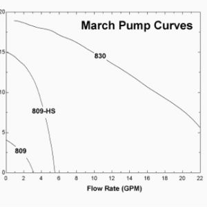
The next step is to determine the proper pump and pipe size that will be able to circulate fluid through the array. The sizing of pumps and piping in solar thermal systems is determined by fluid velocity within the pipe. At velocities beyond 5 ft/sec for heated fluids, erosion corrosion begins to occur when the turbulent scouring action of the fluid eats away at the pipe wall. For any branch within the loop, determine what the flow requirements are, and using figure 1, follow that flow rate until you intersect the 5 ft/sec line. Any pipe selection to the right of that intersection will yield fluid velocities below 5 ft/sec. After you have selected a pipe size, look for where the line corresponding to that pipe size crosses the design flow rate. Following that intersection to the left of the figure will give you the pressure drop in psi for every 100 ft of tube.
The actual pressure drop through any branch depends on the equivalent length of tubing in that branch. The words ‘equivalent length’ are used because elbows and fittings within pipe increase the equivalent length of any piping network. To calculate the length, use table 1 to determine the equivalent length of all the fittings in the branch that you will then add to the straight length. You can now use this equivalent length together with the pressure drop per 100 ft to determine the pressure drop in the loop.
The pressure drop through the collector row can be approximated by taking half the flow rate through the row and assuming that that flow rate travels through the combined distance of the upper and lower headers. As an example, an array row of eight 4 x 10’s should have a flow rate of 8 GPM, half of which would be 4 GPM. With a header length of 4 feet per collector, the upper and lower headers are 32 feet long for a combined length of 64 feet. If the headers are 1″ type M then the pressure drop at 4 GPM is 0.5 psi per 100 feet, or 0.32 psi for the 64 feet in the headers. As you can see, the pressure drop through the collectors is often a small part of the overall losses with most of the pressure drop occurring in the longer supply and return lines.
As final notes, the installer should be aware that the increased viscosity in glycol systems typically increases the pressure drop by 20% over the calculations described above, which are for water. This needs to be accounted for when sizing the pump. Also, in drainback systems, the pump must not only overcome the frictional head losses calculated here, but also the static head losses necessary to raise the fluid from the drainback tank to the top of the array.


