Designing a Solar Heating System
Application Statement:
An apartment complex in Sacramento California wants solar. The complex is a single building with 55 units. 10 of the units are triple bedroom, 10 units are double bedroom, and the remaining 35 are single bedroom. Design a suitable system.


1. Sizing the Array
Using the table from section 1, we see that triple bedroom units have a daily draw of 45 GPD, doubles 35 GPD, and singles 20 GPD. The total draw for the complex is therefore 1,400 GPD [10*45+10*35+35*20].
Well water temperatures in this region are approximately 62 F so the sizing ratio would be 0.71 ft2/GPD [1.15*8.34*(135-62)/984] assuming we used painted collectors in this temperate region.
The total array area is therefore 996 ft2 [0.71*1,400]. Assuming we used EP-40 collectors with an area of 40.8 ft2, the total number of collectors is 24 collectors.
2. Choosing the System Type
Because Sacramento does experience frequent winter freezes, we will want to go with a indirect system. While we have the option of drainback or glycol, we will assume there is a need for simplified piping runs at this site and will choose glycol.
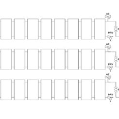
3. Laying out the array
Because it is a 24 collector indirect system, it would look exactly like the glycol diagram shown in section 3
4. Sizing the Heat Exchanger
24 Collectors at 40.8 ft2 each yields an installed array area of 979 ft2. For the SPL31 series, the number of plates would be 108 (979/9), which we would round up to 110 plates. For the SPL110 series, the number of plates would be 20.
Since the minimum number of plates available on the SPL110 Series is 30, we would opt to go with a 110 plate SPL31 unit (Model # SPL31-110)
5. Sizing the pump and piping
With a design flowrate of 1.04 GPM/collector, the total array will require 25 GPM of flow. Using the chart in section 5 we see that the smallest pipe size that can handle this flow rate is 1.5″ piping. This will be the size of the main supply and return runs. The pressure loss per 100′ of 1.5″ type M tubing at 25 GPM is approximately 2.6 psi.
Because we have 3 rows of 8 collectors each, we can use 1″ headers. From section 5 we determine the pressure loss in the collector row to be 0.32 psi (4 GPM average going through 64 feet of 1″ header). From section 4 we see that average pressure losses through the SunPlate heat exchanger are 1.5 psi. If the equivalent pipe run length is 100′ round trip accounting for all fittings and valves, then the overall loss is 4.42 psi [2.6+1.5+0.32], which is equal to 10.2 feet of head. Since the fluid is glycol, we will add 20% to the head to account for viscosity. The design pump pressure is therefore 12.3 feet at 25 GPM. Looking at the pump curves in section 3, we see that these pumping requirements can be met by a Grundfos 43-75F circulator or a Taco 0013.
For optimal heat exchanger performance we want to pump the potable side at the same flow rate as the glycol side (25 GPM). Because the flow rate is the same, we will use 1.5″ pipe with a pressure drop of 2.6 psi per 100′. If the potable recirc loop has an equivalent length of 30′ then the total potable loop pressure drop including the heat exchanger would be 2.3 psig [30/100*2.6+1.5], or 5.3 feet. For this low head application, suitable pumps would be a Grunfos 26-96BF or 43-75BF, or a Taco 0012 or 0014.
6. Sizing the Storage
According to section 6, the ratio of storage volume to collector area would be 1.2 gal/ft2 [120/(160-62)]. The total storage for the array would be 1175 gallons (979*1.2). We would likely choose the closest size ASME tank greater than 1175 gallons that would fit at the site. If that size storage could not fit, we would have to reduce the size of the array for a smaller tank.
7. Sizing the Drainback or Expansion Tank
To determine the size of the expansion tank we need to determine the indirect volume. At 1.2 gallons capacity per collector, the array holds 29 gallons (1.2*24). For 1.5″ type M piping, the fluid capacity is 9.5 gallons per 100′. The total loop volume is therefore 38.5 gallons (29+9.5). Looking at the chart of expansion tanks in section 7, either an Extrol #90 or an Extrol SX-30V would be sufficient for the application.
A Review of System Performance
The 2 graphs above show the simulated operation of the system we just designed. Solar tank temperatures illustrate the difference in Sacramento’s cool cloudy winters and hot central valley summers when it reaches the design value of 160 F.
Likewise, the system energy output shows over a 90% solar contribution through the summer falling off to 20-40% in the cloudy winter months.
The annual solar fraction for this system would be 64%, which is in line with the most that could reasonably be expected for that climate.
Additional Water Heating Designs
SunEarth advocates the use of indirect systems with glazed panels for pools operated year round for several reasons.
Learn More